Task
Solution Services was tasked with performing the engineering required to facilitate the installation of a second paper-treating production line adjacent to the existing production line located at a paper-treatment facility. This included equipment layouts, enclosure design, pipe routing, ducting and associated supports, HVAC, electrical, and civil site work.

Execution
Ducting & Duct Supports
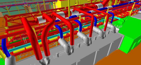
Production Line 2’s ducting requirements included three major ducts, the largest of which measures 5′-10 7/8″ in diameter at the north end of the line. Each of these was wrapped in 3-4″ of insulation and two required expansion joints due to the operating temperatures inside of them. Numerous simulations were run on our ducting models to determine the necessary number and best placement of the expansion joints. Further simulations and finite element analysis were performed on the support structure itself as we tied it into the existing support structure. On Production Line 1, the ducting was located directly over the line, but for Production Line 2 the ducting runs between the lines to make use of the existing structure.
Due to this, an additional structure was required to support each of the many branches connecting to the equipment and the FEA was further complicated as connections to the equipment were not in line with the duct.
The structure required to support this ducting as well as cable trays and piping in some locations was designed using HSS posts and I-beam cross members. Solidworks structural analysis helped us determine steel sizing and locations of bracing and further supports. Where possible, existing structures and the new enclosures were tied into, however north of the interior partition wall, and on the exterior of the building, separate support structures were required.
Enclosure Design
Structures were required to enclose three parts of the line, creating small rooms that allow for operator and maintenance access. Each of these needed to be individually assessed for structural integrity depending on the loads that would be placed on their roofs, including blowers, chilled water skids, and HVAC. Additionally, the ducting support structure ties into these enclosures due to space constraints and the need to avoid placing posts in front of access doors on the equipment. These variables, along with client requests, led to these enclosures being reworked and redesigned around a dozen times throughout the course of the project.
Piping
Production Line 2 required compressed air, chilled water, and natural gas for the process as well as hot water for additional safety showers. Modifications were made to existing P&IDs and new ones were created to design each system. These lines were then routed in coordination with other models of the facility using AutoCAD Plant3D and Navisworks. Existing systems were tied together and the chiller system was expanded by adding a second chiller and buffer tank to account for the increased demand.
Conclusion
This project offered a diverse set of challenges and touched on many different skill sets such as piping system design, three-dimensional modeling, structural and finite element analysis, and more. Consistent client reviews and communication allowed us to convey progress, request necessary information, and provide the client with a comprehensive final product.
